3DPrintCAD › Guides › Port holes tool
Port holes tool: cut USB, HDMI and connector openings in a 3D model
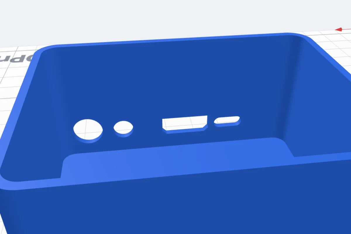
An enclosure for an electronics project needs openings for its connectors - a USB-C port, an HDMI socket, a power jack, a button, an LED. The Port holes tool cuts them into any flat face of a body you already have: pick the connector, drag it into place - its distances to the face's edges show in red - or type them exactly. Each opening is the connector's real outline, a little bigger so it fits a printed part.
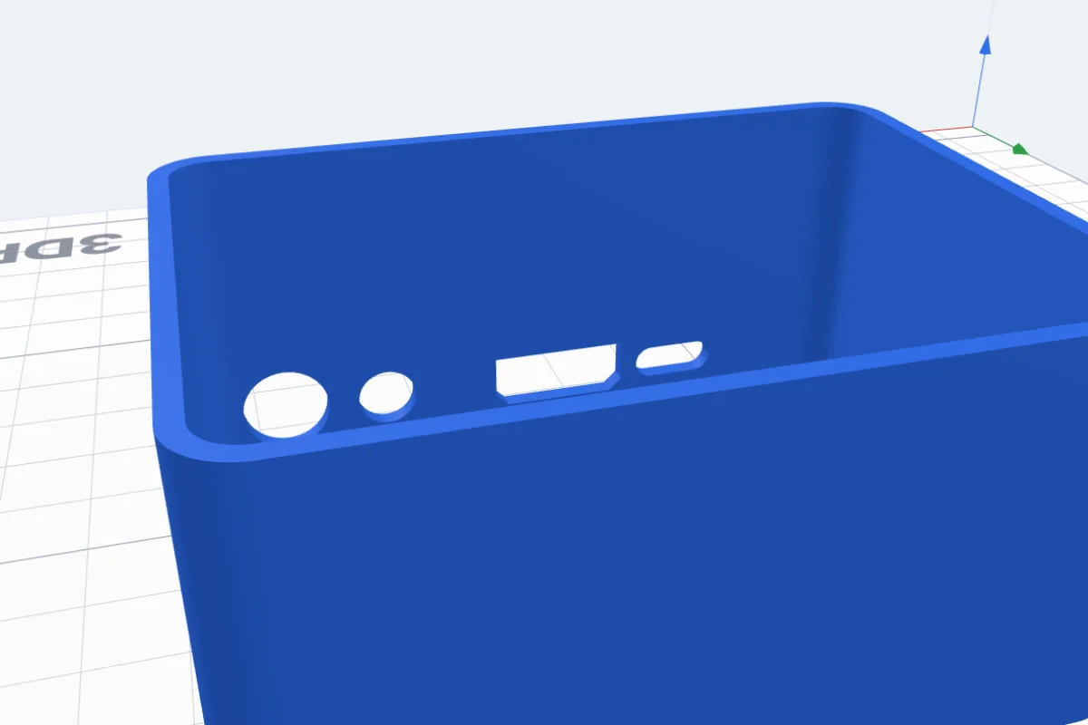
Watch the tutorial
Every step in under three minutes, narrated with subtitles: pick a face, the connectors, exact distances, fit, depth and cutting. Watch on YouTube ↗
1Pick a face
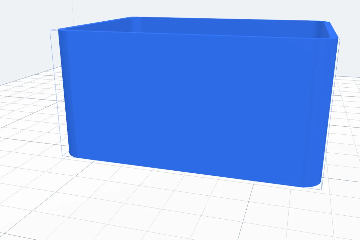
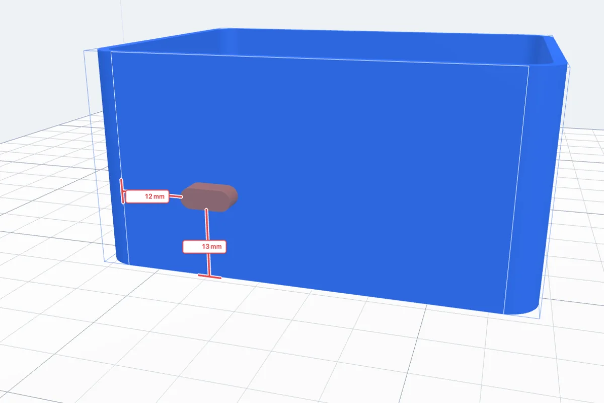
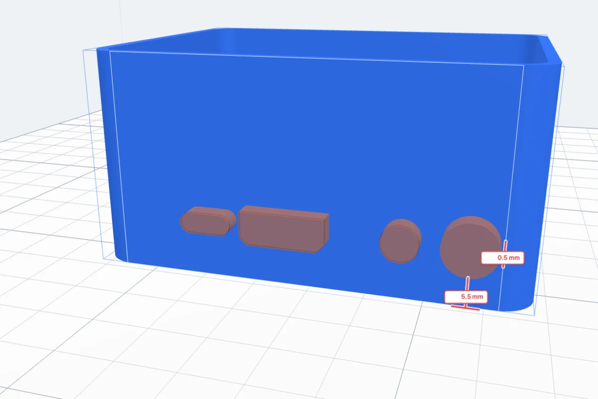
Select the body (an enclosure, a box, a case) and click Port holes in the Body card. Move the mouse over the body: the flat face under it lights up. Click the face where the first opening goes - a USB-C opening appears there, with its distances to the face's nearest edges in red.
2Choose the connector
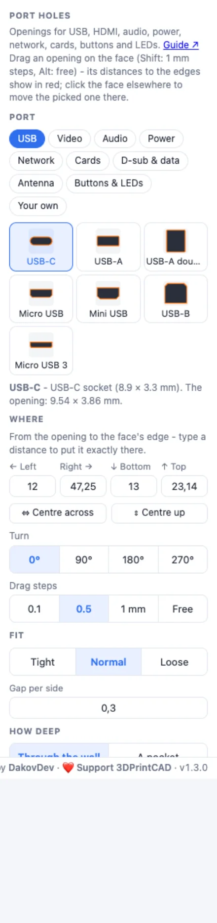
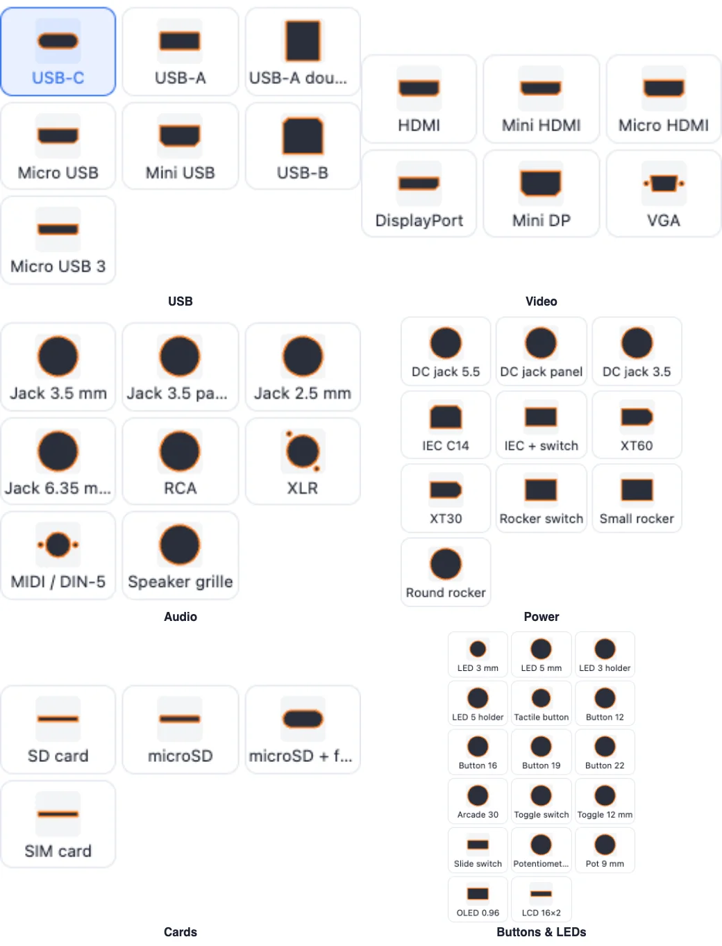
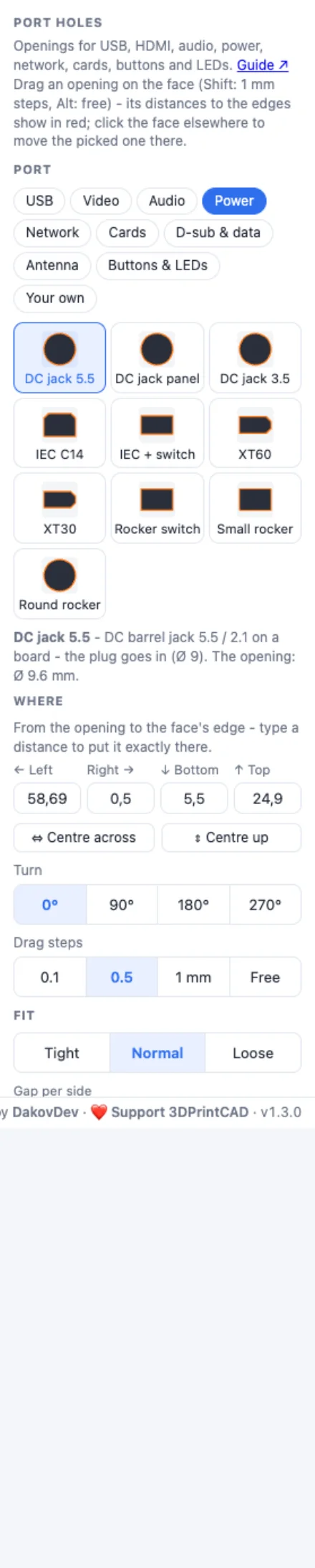
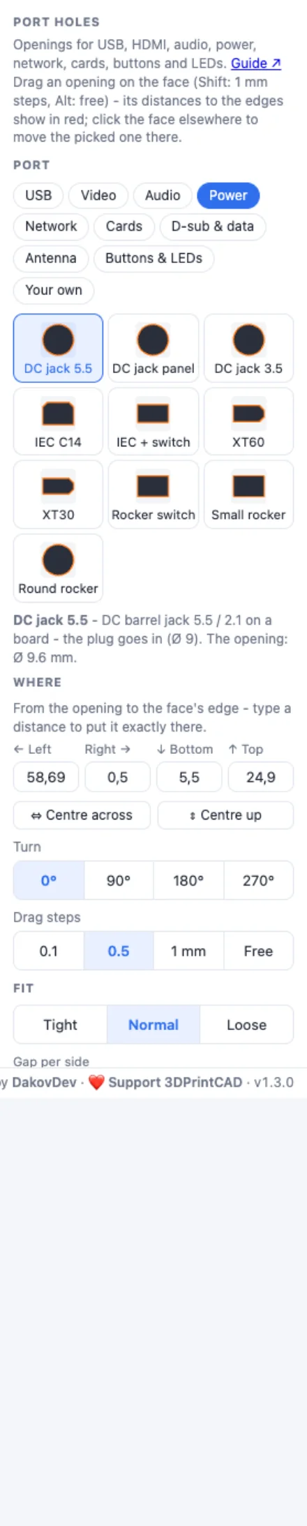
Pick a group - USB, Video, Audio, Power, Network, Cards, D-sub & data, Antenna, Buttons & LEDs or Your own - and a connector: each tile is drawn from its real outline. The panel names it, says what it is and gives the opening's size. Your own takes a rectangle (with its corners), a circle or a slot of any size.
3Place it exactly
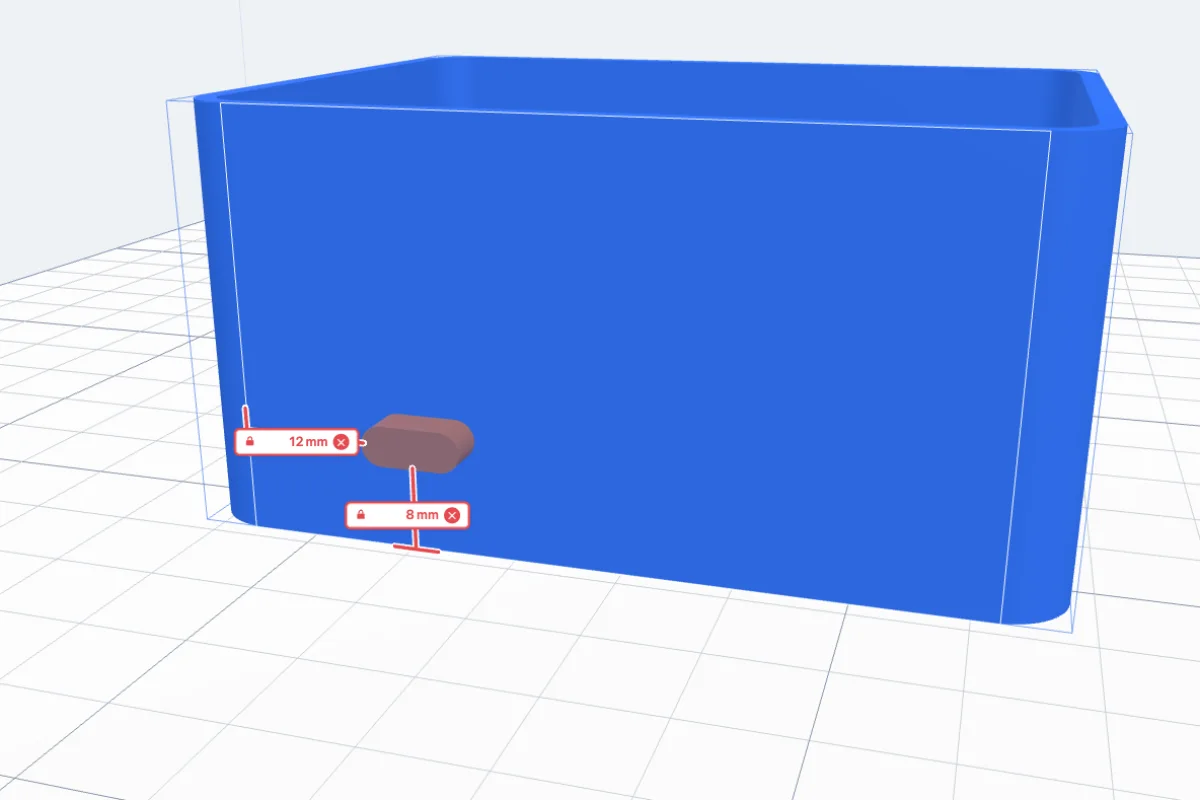
Drag the opening on the face - it snaps so its distances to the edges are whole steps (Drag steps 0.1, 0.5 or 1 mm, or no steps at all; Shift for 1 mm, Alt for no snapping). Click the face anywhere else to move it there. The red lines always show the nearest side and the nearest top or bottom.
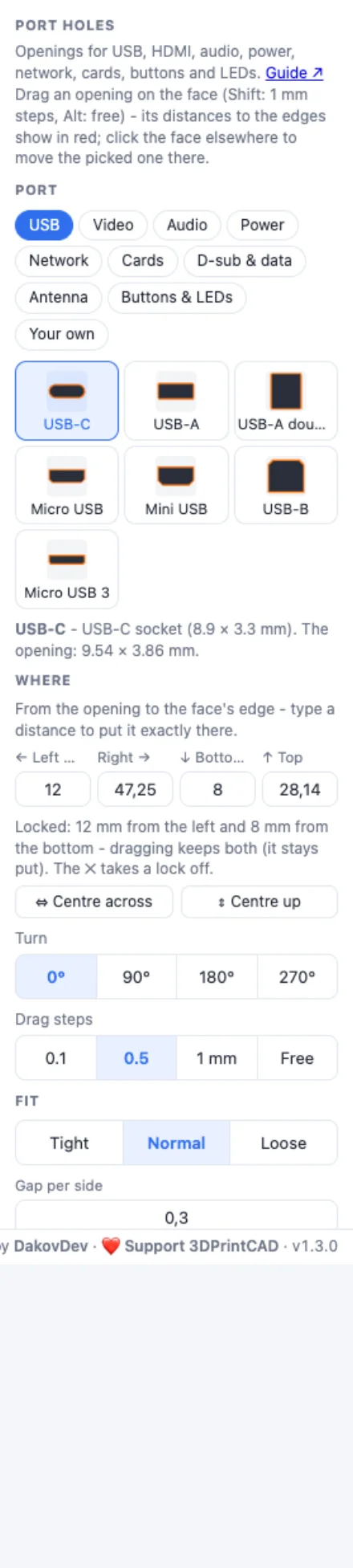
To put it exactly: type a distance into Left, Right, Bottom or Top - in the panel or straight into the red label in the view - and press Enter. The opening moves there and that distance is locked (a lock icon): a drag then moves it only the other way, and changing the connector keeps it. The red ✕ takes the lock off; Centre across and Centre up put it in the middle. Turn it 0°, 90°, 180° or 270°.
4Fit, depth and more openings
Fit - how much bigger than the connector the opening is on every side: Tight 0.15, Normal 0.3, Loose 0.5 mm or any gap. How deep - Through the wall or A pocket of a depth you set.
+ Add another puts one more opening beside the picked one (on the first open place right, left, above or below) - then pick its connector. Every opening on the face is listed under Openings on this face: click one to pick it, ✕ to remove it. The panel warns when an opening runs past the face's edge or two run into each other. Pick another face starts again on another face.
5Cut them
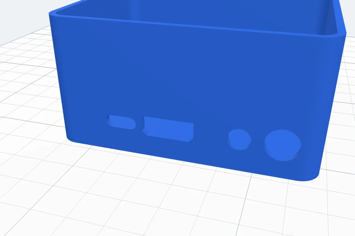
Click Cut N openings: every opening is cut into the body at once (one undo step, Ctrl+Z brings the face back).
Questions
Which connectors are there?
About 70, in ten groups: USB (C, A, A double, micro, mini, B, micro 3.0), Video (HDMI, mini and micro HDMI, DisplayPort, mini DP, VGA), Audio (3.5, 2.5 and 6.35 mm jacks, panel jacks, RCA, XLR, MIDI, a speaker grille), Power (DC jacks, IEC C14 with or without a switch, XT60, XT30, rocker switches), Network (RJ45, RJ11, SFP), Cards (SD, microSD with a finger notch, SIM), D-sub & data (DB9, DA15, DB25 with screw holes, PS/2, a cable slot, a cable hole), Antenna (SMA, BNC, N, F), Buttons & LEDs (3 and 5 mm LEDs bare or in holders, tactile buttons, push buttons 12-30 mm, toggles, a slide switch, potentiometers, OLED and 16×2 LCD windows) and Your own (a rectangle, a circle or a slot of any size).
How big is the opening?
The connector's front plus the fit on every side: Tight 0.15, Normal 0.3 (the default) or Loose 0.5 mm, or any value you type. Printed holes come out a little small, so Normal suits most printers; the panel gives the opening's exact size. Check your connector with a calliper - the sizes are the usual ones.
How do I place it exactly?
Type a distance into Left, Right, Bottom or Top (in the panel, or in the red label in the view): the opening moves there and that distance is locked - dragging it then only moves it the other way. Lock one side and one of top or bottom and it stays put. The ✕ beside the lock takes it off; Centre across / Centre up put it in the middle.
Can it be a recess instead of a hole?
Yes - How deep: A pocket cuts only as deep as you set, for a label, a display bezel or a socket glued in from the front. Through the wall cuts right through the wall under the opening.
Does it work on any body?
On any flat face of any body - a box from the Box generator, a board case, an imported STL, a shape you made. The face must be flat; for a curved wall use the Hole pattern or a sketch.
Cut the openings for your next enclosure
Pick the face, the connectors and their places - and cut them in one go.
Open 3DPrintCADAlso see: Board case generator, Box generator, Hole pattern tool and Bolt generator.